Vfd Schematic Diagram Circuit Diagram Step 2: Design the Power Circuit. The power circuit consists of the rectifier, DC bus, and inverter. Follow these steps to design the power circuit: VFD schematics provide a visual representation of a Variable Frequency Drive's internal circuitry, helping technicians understand its operation and troubleshoot issues. By familiarizing Building a VFD from scratch can be a complex and time-consuming process, but it can also be a rewarding learning experience. Here are the basic steps to build a simple PWM VFD: Design the power circuit, including the rectifier, DC bus, and inverter; Select the appropriate components, such as diodes, capacitors, IGBTs, and gate drivers

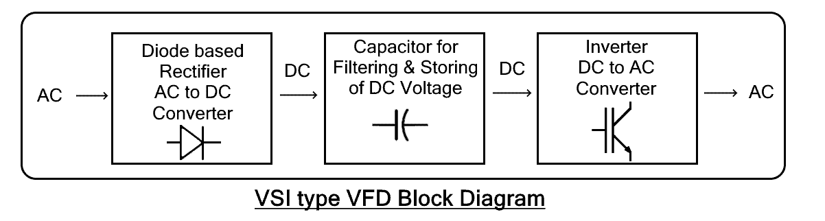
Figure 2 - VFD Circuit Diagram. Go back to the Contents Table ↑. 2.1. Working Principle. It is important to be familiar with the working principle of VFDs as they are extensively used in AC motor-driven applications.VFD has greater functionality and operation capabilities than conventional motor drives, which will be explained in detail in this article. The VFD circuit diagram may also include additional components, such as capacitors, resistors, diodes, and filters, depending on the specific design and requirements of the system. These components are used to ensure proper power conditioning and to protect the VFD system from voltage spikes and other electrical disturbances.

Single Phase Variable Frequency Drive VFD Circuit Circuit Diagram
Variable Frequency Drive (VFD) - Circuit Diagram, Working, Types, Advantage, Disadvantages, and Applications. Types of VSI, CFI and PWM VFDs. Breaking News. 50% OFF on Pre-Launching Designs - Ending Soon ; Special Motor Design: The PWM-based AC output of VFD is not pure sinusoid. It can create stress in the windings of a normal AC motor

The output of this inverter is used to control the desired motor, whose speed need to be controlled as per the VFD rules. In order to convert this square wave inverter into a sine wave VFD circuit, I have configured an adjustable SPWM generator stage using the IC 555 astable and an op-amp comparator.
Phase Variable Frequency Drive (VFD) Circuit Diagram
Step 3: Design the Power Circuit. Design the power circuit of the VFD schematic, which includes the rectifier, DC bus, and inverter sections. Determine the appropriate component values, such as capacitor size and inductor ratings, based on the system's power requirements and desired performance. Step 4: Develop the Control Circuit